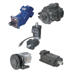
Hydraulic Pumps: Fixed Displacement Gear Pump


When gears are meshed, they will spin in opposite directions. Gear pumps use this fact to move fluid from one side (Inlet) of the gear set to the other (Outlet). The gears will move toward the flow of oil coming into the Inlet port. As oil enters, it is grabbed by the gears and moved along the outside of the gear set along the gear housing. You can see this flow in the picture below. As the fluid enters the Outlet side of the pump the fluid is forced out of the pump and routed to other portions of the hydraulic circuit. This process continues as long as the pump is spinning. Every revolution of the pump shaft will always let a certain metered amount of fluid out of the pump. This is why it is called a fixed displacement pump.
How Does a Fixed Displacement Gear Pump Work?
A fixed displacement gear pump is designed to pump a constant metered amount of hydraulic oil. The job of the pump is to create the flow that is required in a hydraulic system. One common misconception is that the pump creates ‘pressure’. Pressure is created when there is an opposition to the flow of fluid in the system. The purpose of this article is to explain the operation of a gear pump while breaking down the internal components that make up this important component.
Gear Pump Components and Assembly
A gear pump is a relatively simple device that is made up of only a few standard components. Let’s build one together!
We'll begin with the front cover assembly. The front cover consists of a flange mounting surface, shaft seal, bushings or bearings, and the thrust plate and seals.


Step 1:
Press the shaft seal into place using a press.
Step 2:
Insert the rubber seal and nylon insert into the thrust plate. For clockwise rotation pumps, the seal will be located face down on the right side of the pump. For counterclockwise rotation pumps, the seal will be located face down on the left side of the pump. Orientation of the thrust plate seal is crucial for correct operation of the pump.
Step 3:
Install the 2-4 dowel pins by lightly tapping with a hammer if necessary.
The ‘Gear Housing’ portion of the pump consists of a seal on either side and supports the gear set.
Step 4:
Install the 2-4 dowel pins by lightly tapping with a hammer if necessary.
The ‘Gear Housing’ portion of the pump consists of a seal on either side and supports the gear set.


Step 5:
Apply a small amount of ‘Moly’ to the seal groove on the gear housing and install the seal.
Step 6:
Install the gear housing on the pump. Locate the directional arrow on the outside of the housing and make sure it corresponds with the pump direction. There are also two cavities on either side of the bearing slots. The larger cavity is the inlet side of the pump. Use a rubber mallet to seat the gear housing to the front cover.
Step 7:
Install the seal set on the second thrust plate. Apply a small amount of ‘Moly’ to the bearing side of the thrust plate before installing on the gear set. The bearing surface should be installed facing down and sealed on the side that matches the rotation of the pump.
Step 8:
Install the 2-4 dowel pins into the gear housing.
Step 9:
Apply a small amount of ‘Moly’ to the seal groove and install the seal.
The end cover section usually houses the inlet and outlet ports. It will also contain either a set of bushings or bearings to support the end of the gear set.
Step 10:
Install the rear cover. Align the inlet and outlet ports to correspond with the direction of shaft rotation.
Step 11:
Thread in the studs that hold the pump together. Torque down the hold down nuts to manufacturer’s suggested specifications.
Congratulations, your pump is now ready for operation.


